
Digital to Analog Speaker
Feburary 2023
About this project
This project was made for my first Omega Lab in Introduction to ECSE. We were required to pick one main circuit concept to develop our design around and one output device. The concept we chose was voltage dividers, with a common application of them being used in R-2R ladders for Digital to Analog converters (DACs).
To create the four-bit DAC, we used a four-bit R-2R ladder where each voltage input corresponds to a single bit. The R-2R works due to the principle of superposition, where the left most resistor is the LSB contributing the least to output value, and right most contributing the most. This results in an analog value found by converting a four-bit number. In the simulation, 0V was treated as binary low, and 5V as binary high. With the input voltage of 0001, the Vout was successfully found to be -1, which was due to inverting amplifier that we used.

Finally, using a waveform generator, we were able to see the outputted analog signal of the circuit. While the shape has some discrepancies, it is clear that the digital signal was successfully converted into an analog circuit. The output of the speaker can be found below!
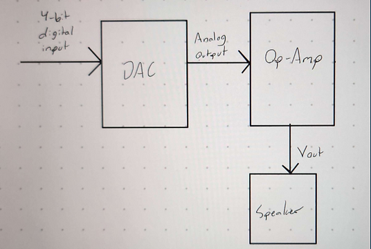
The components of the project were relatively simple. We were going to create a four-bit digital signal, convert it into an analog signal using the DAC, and then send that to an op-amp for amplification. Then it would be outputted through a speaker.


For the implementation of the design, we decided to use the AD5626 IC for simplicity. It had a 12-bit R2R DAC converter and non-inverting amplifier built in, which made our design much more accurate to what we wanted.
